

Cockpit panels might look simple, but their design and manufacturing involve a precise process. In this article, I’ll take you through the making of my UHF panel, step by step, from research to laser engraving.
Step 1 – Research and Geometry
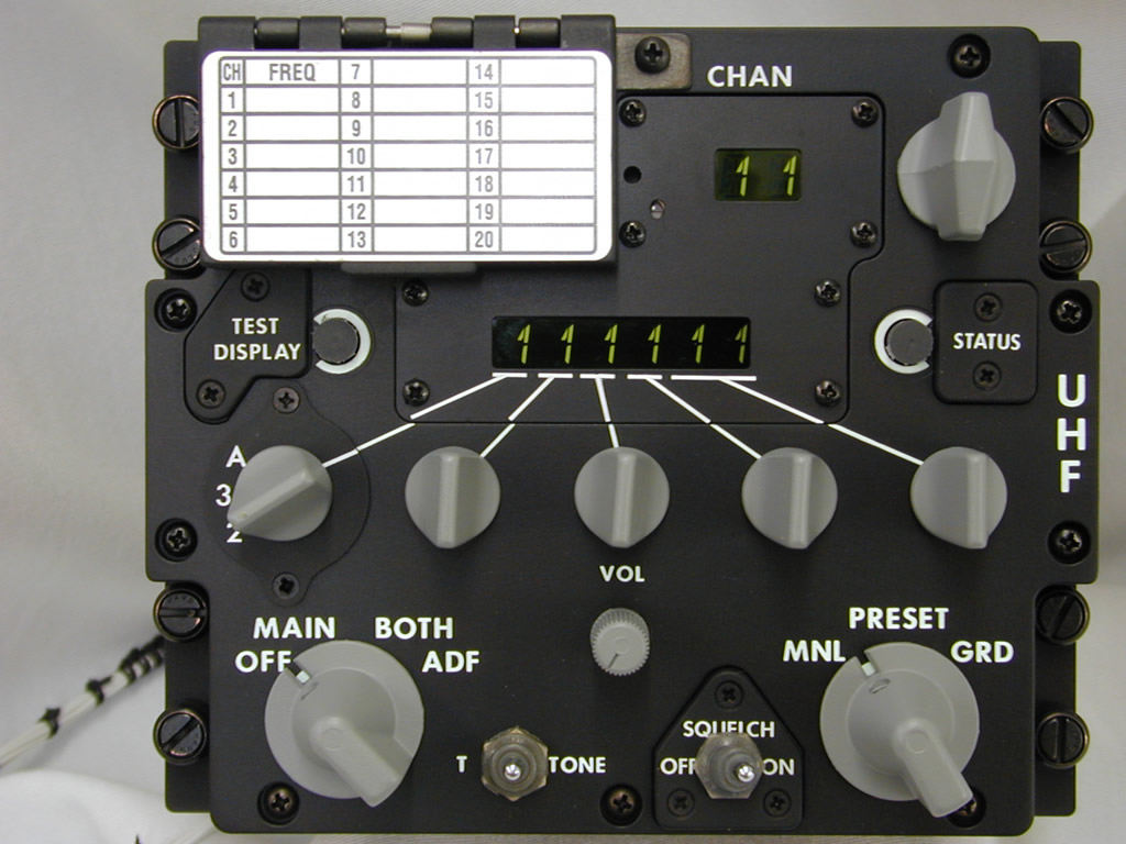
The first step is to gather information about the panel: its geometry, layout, and lettering.
For this, the best photo references can be found on xflight.de and viperpits.org.
The standard panel width is 144 mm. With this reference and good photos, it’s possible to correctly place the main holes. Later, I received the UHF board from PS Cockpit and used calipers to take precise measurements directly from the PCB.
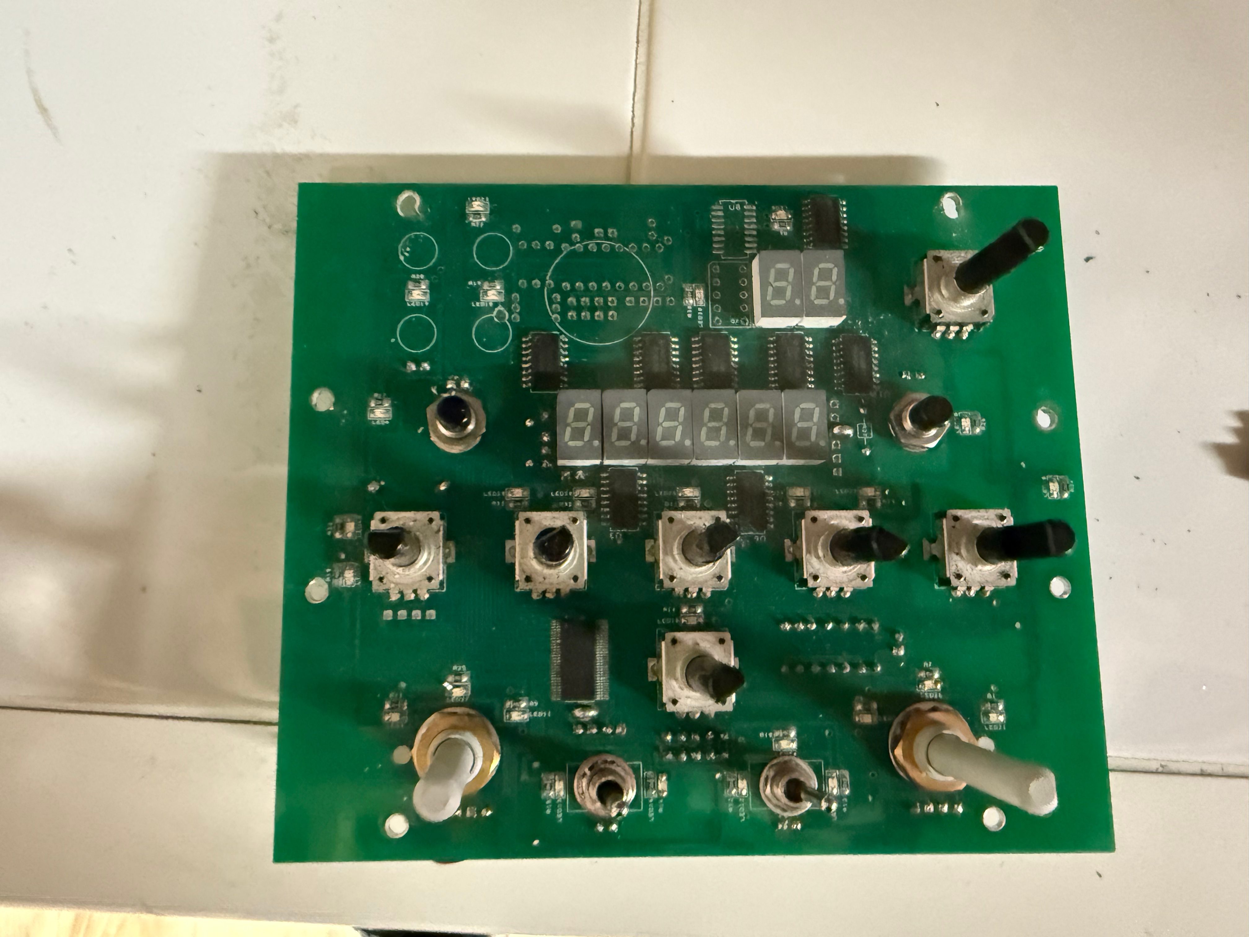
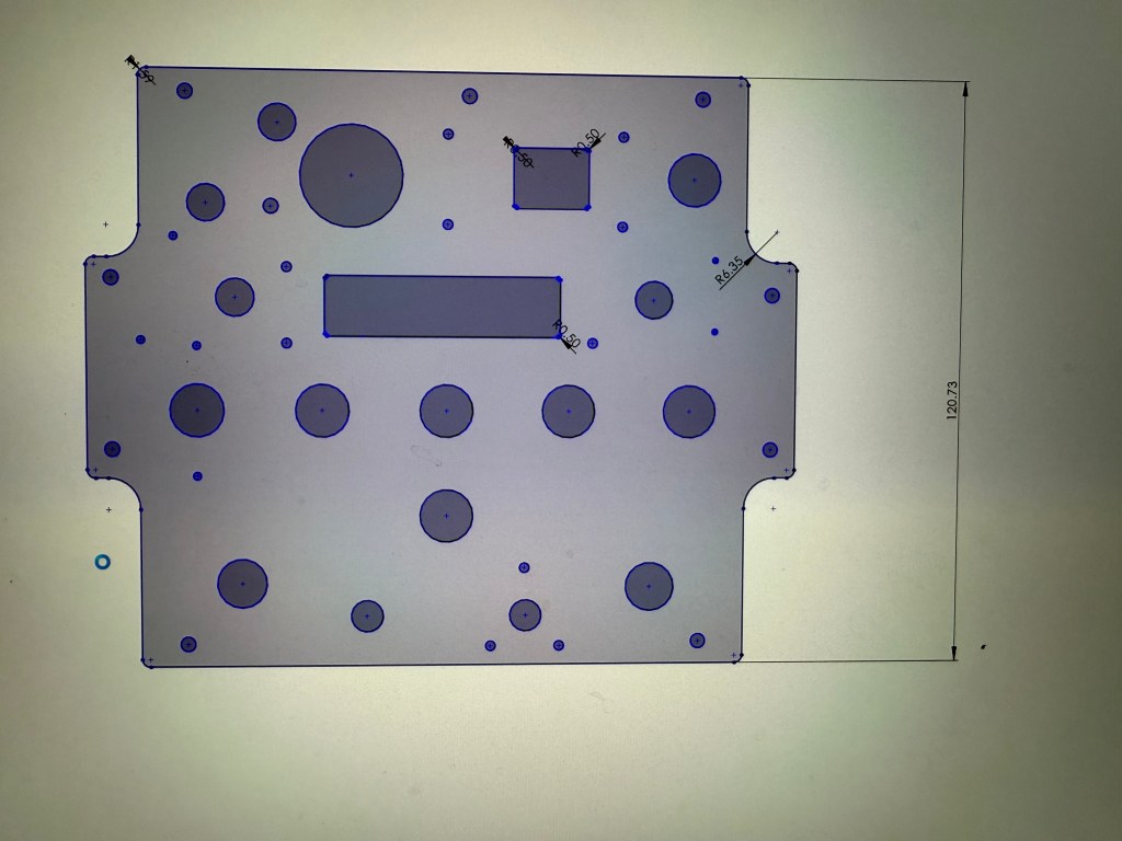
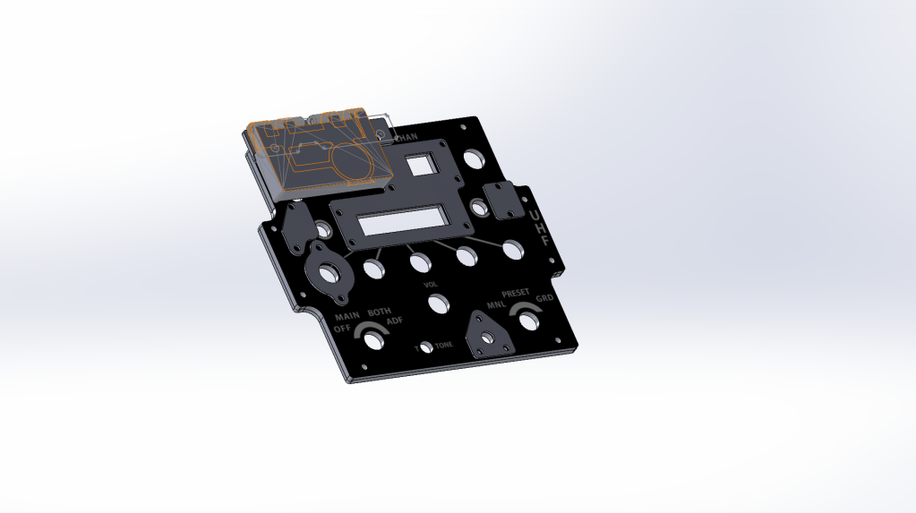
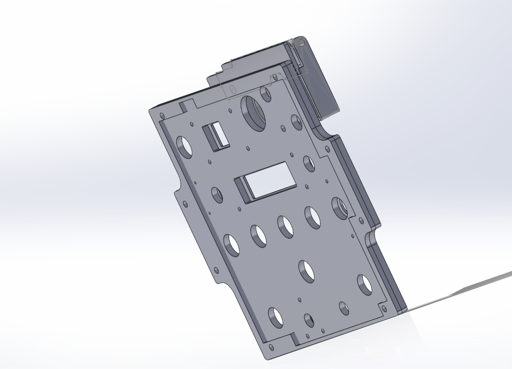
From there, I created an approximate CAD model of the board. This served as a base to build an assembly with all the other elements of the panel, ensuring proper alignment of holes and mounting points.
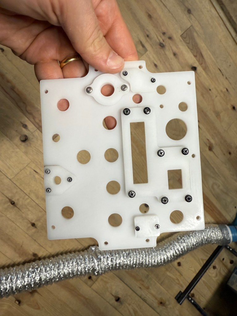
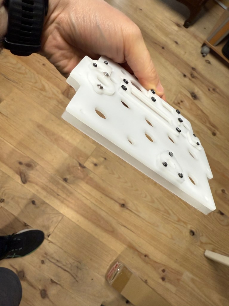
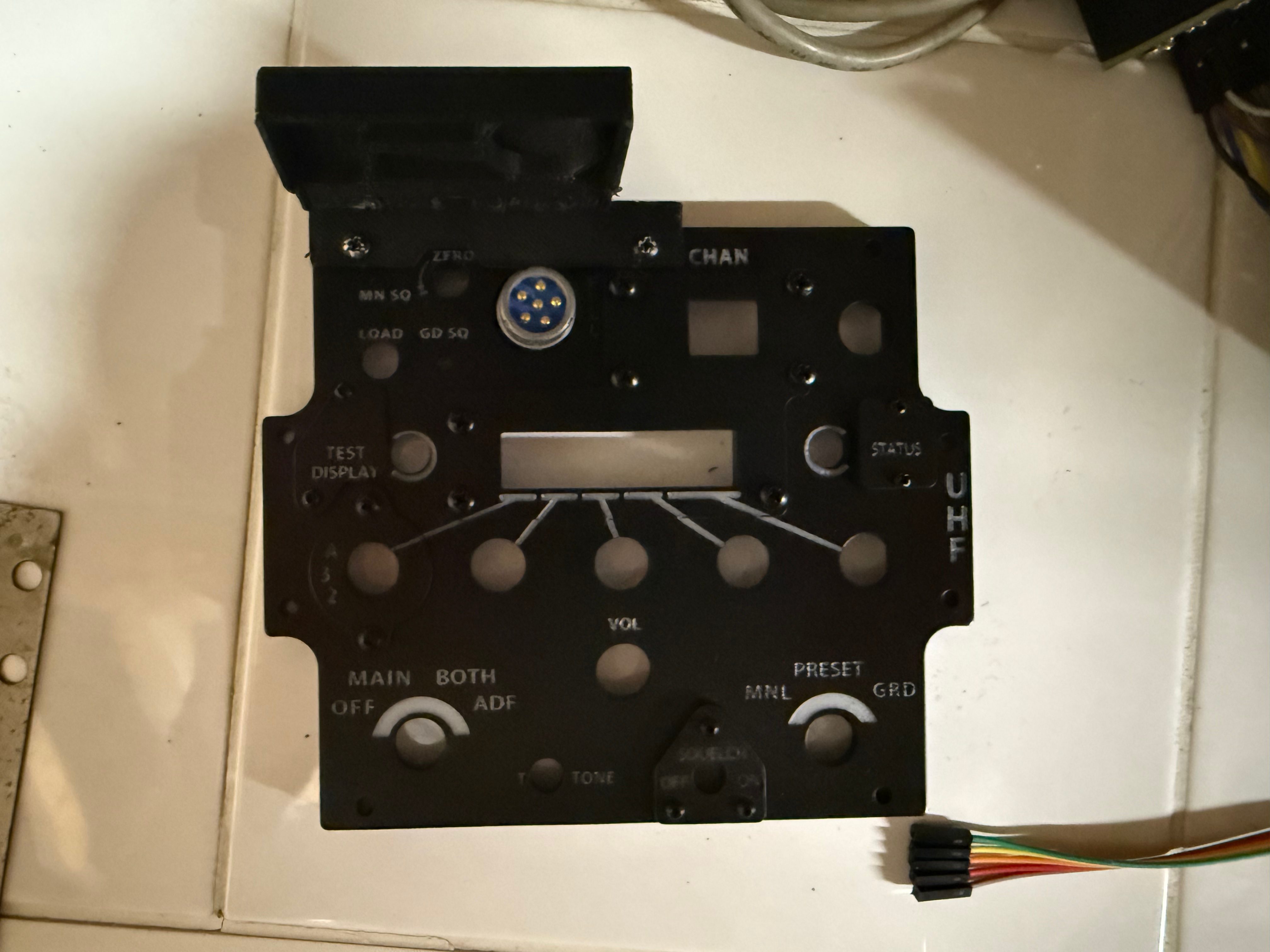
I also designed the small additional parts that screw onto the panel surface. These visible screws not only serve a structural purpose but also add to the panel’s realistic aesthetics.
Step 2 – Preparing the CAD Files
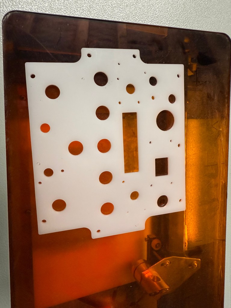
To reproduce the backlit effect, the panel is made of two layers of white PMMA:
- 4 mm base plate, cut with the openings,
- 2 mm front face, later painted black and engraved.
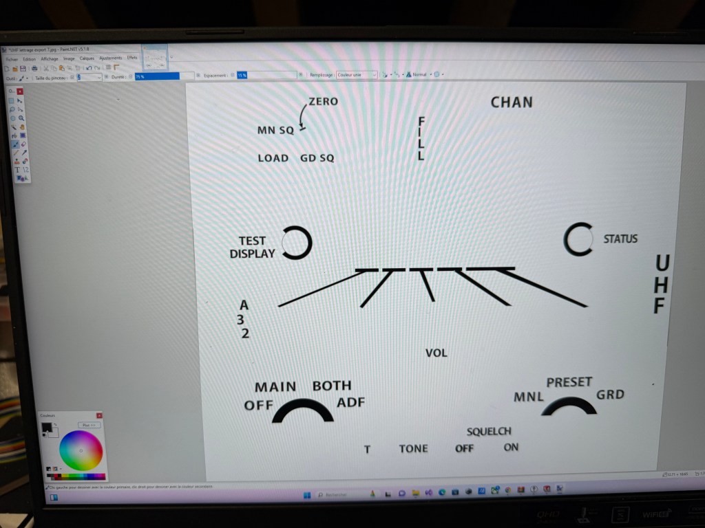
The lettering was designed directly in CAD, using the dedicated cockpit panel font available on viperpits.org. Once the text was placed, I exported the design as a high-resolution JPEG.
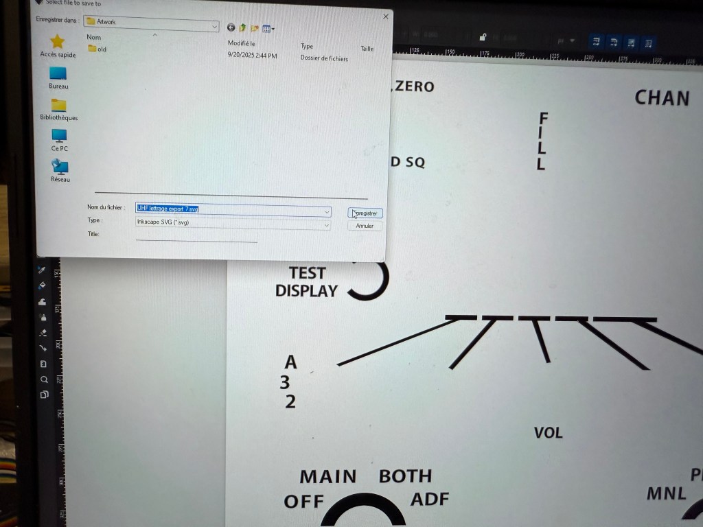
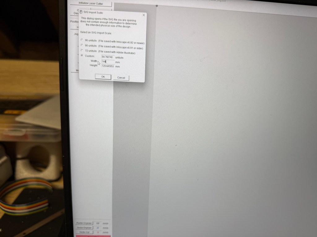
This image was then reimported into CAD to double-check alignment with the drill holes. Once everything matched, I exported the file into Inkscape and converted it into an SVG file—the only format Whisperer accepts for engraving.
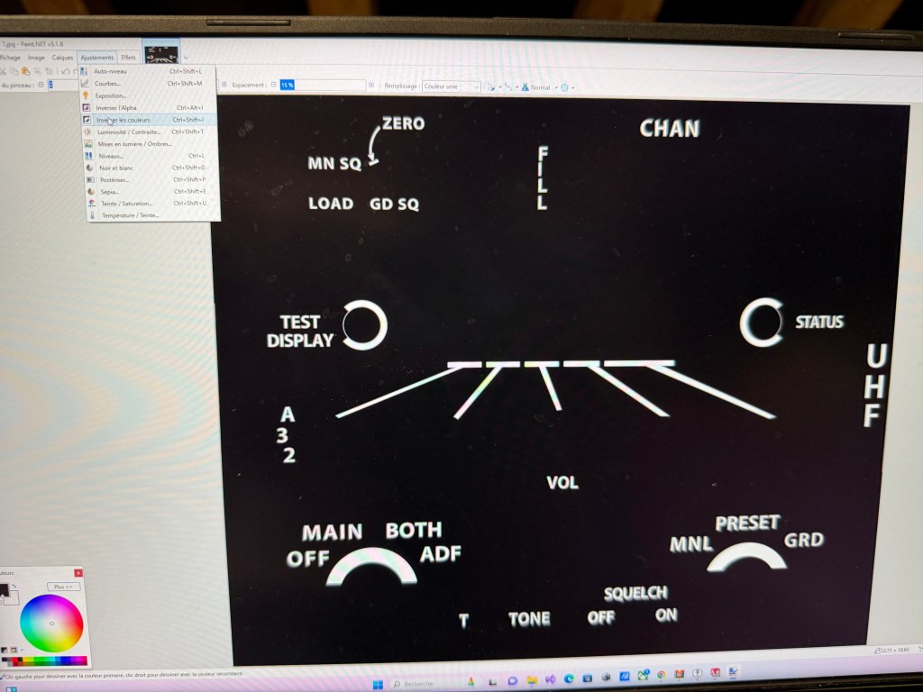
👉 Important note: Whisperer interprets colors as laser power levels. White = 0% (no laser), Black = 100% (full laser). This means you need to invert the colors of your lettering before importing the file into Inkscape.
Step 3 – Cutting with the K40
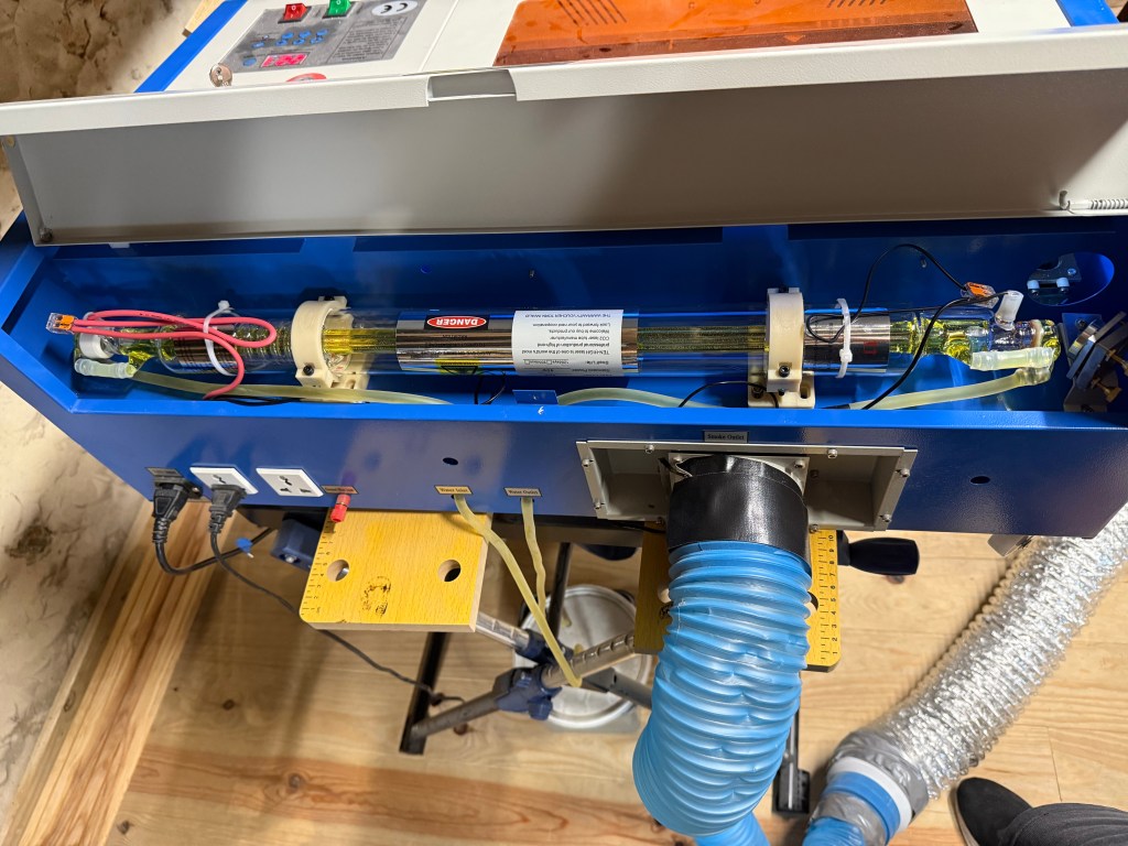
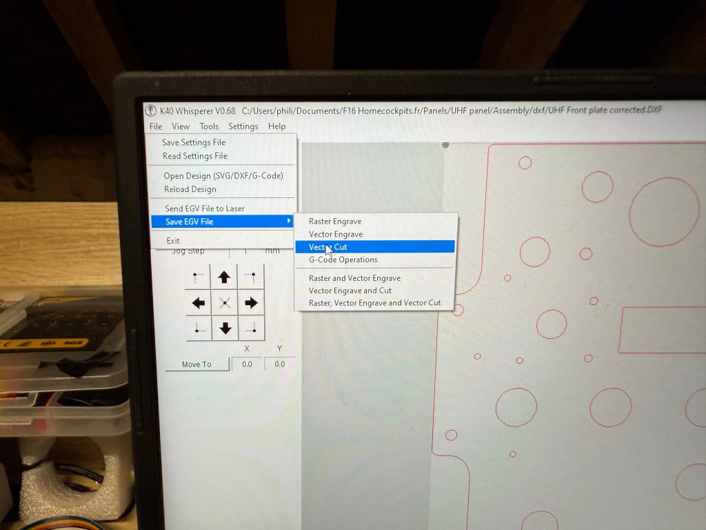
I use a 40W CO₂ laser engraver (K40) with the software K40 Whisperer.

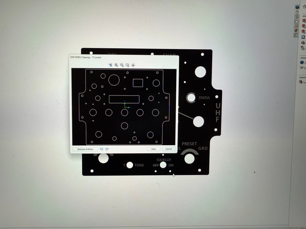
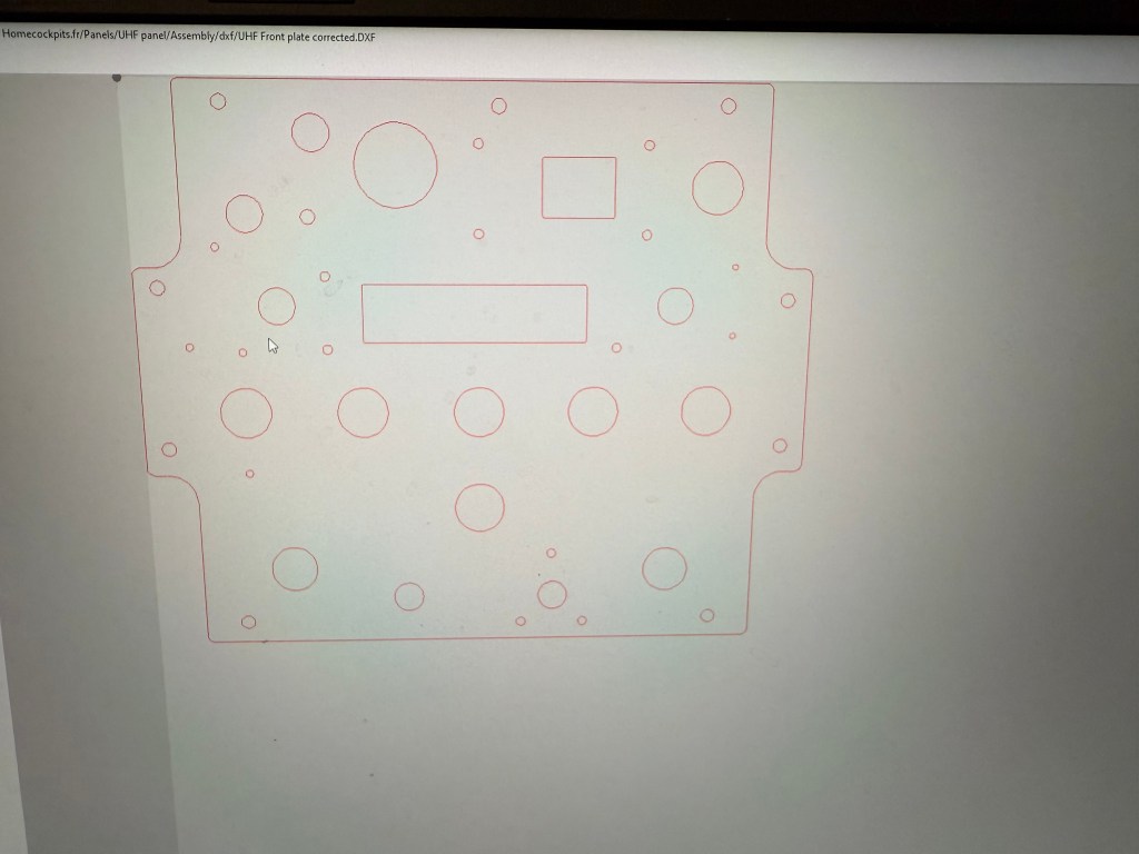
- For cutting: Whisperer works best with DXF files, exported directly from CAD. These are used to cut the 4 mm base plate and the 2 mm top plate.
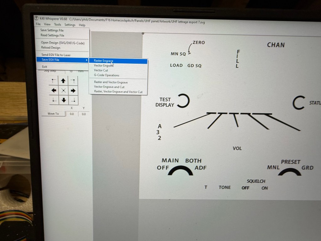
- For engraving: the SVG file generated from Inkscape is imported into Whisperer to create a Raster Engrave file.
👉 Trick for alignment: The rectangular PMMA sheet is always placed against the back edge of the laser bed, serving as a fixed reference. Once the front face is cut, I leave the plate in place. After gluing and painting, I return the assembled panel into the same cutout position for engraving. This ensures that the engraving and the drilling remain perfectly aligned.
👉 Surfacing tip: Laser heats the PMMA and vapors are generated during the process. These vapors leave traces on the surface of the panel and it can create visible areas under paint afterward. To avoid that, I usually sand the panel before paint

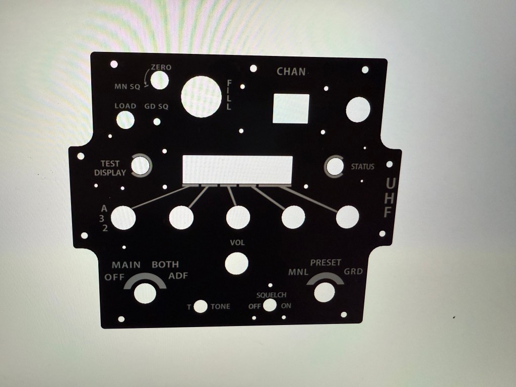
Step 4 – Painting and Engraving
The front plate is sprayed with matte black automotive paint. Once dry, engraving the text reveals the underlying white PMMA, creating the authentic backlit effect.
It’s crucial to work in a dust-free environment during painting, otherwise imperfections will ruin the finish.
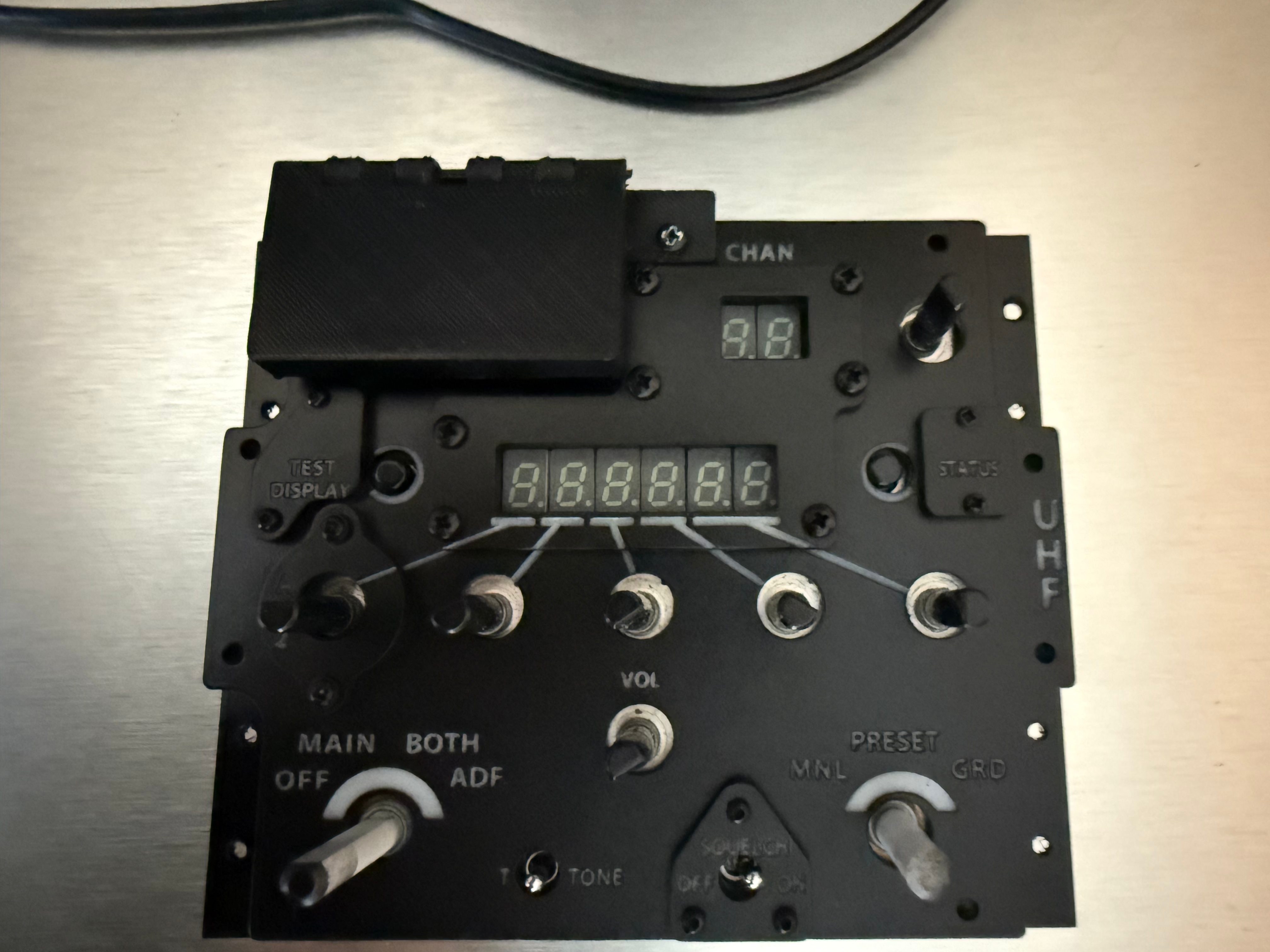
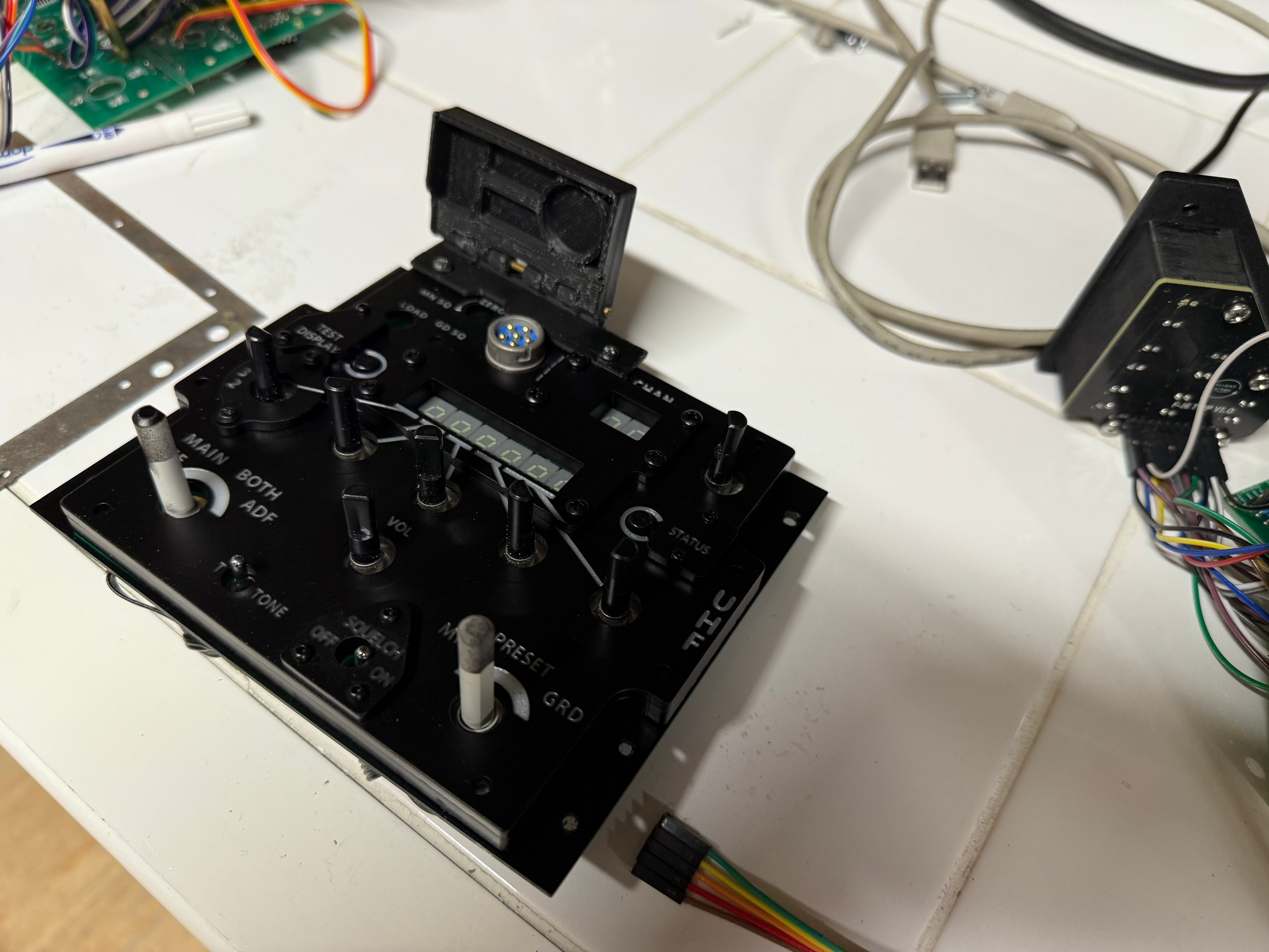
Step 5 – Mounting on Electronics
Finally, the UHF panel is mounted onto the PS Cockpit board. These boards are excellent and will be the subject of a future article where I’ll cover their configuration and integration in detail.
Conclusion
The process may seem complex, but once mastered, it becomes a repeatable workflow for any cockpit panel. From CAD to painting, each step is about precision and patience. The end result is a realistic, backlit, functional panel that looks just like the real thing—and feels even better when installed in the cockpit.

Laisser un commentaire