

Building the Cockpit Structure
Designing the structure of a home cockpit is one of the most exciting—and challenging—parts of the project. My own build was based on plans inspired by Symulate, adapted with the help of dimension references available on Viperpits. By importing the original DXF drawings into a CAD program, it becomes possible to check, refine, and adapt them to your specific needs.
Key Considerations in the Design Phase
When designing the structure, a few important requirements should be part of the initial checklist:
- Space under the panels: Switch bodies and electronic components (wires, connectors, PCBs, etc.) require at least 5 cm of clearance. If this isn’t planned from the start, structural reinforcements may interfere with panel installation.
- Accessibility for maintenance: Electronics will eventually require troubleshooting. Building access panels with proper opening and locking mechanisms makes it possible to reach wiring without dismantling half of the cockpit.
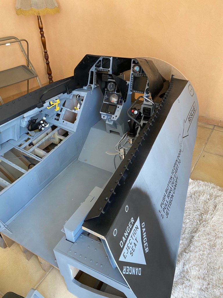
- Materials: Builders working in aluminum can achieve a very clean integration with the outer “skin” of the cockpit. In my case, the main structure was built from MDF wood, with an outer skin made of thermoformable FOREX.
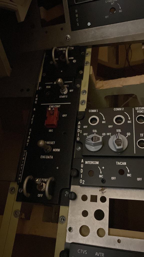
Panel Mounting System
In the real F-16, panels are mounted on DZUS rails. To replicate this system, I used aluminum angle brackets drilled with holes to accept M3 threaded inserts. Panels can then be mounted using simulated DZUS fasteners: essentially M3 screws surrounded by a 3D resin-printed ring or a cut aluminum tube.
This simple system not only holds the panels securely but also provides the look of the real DZUS rails. Everything was finished with a two-component RAL 7001 gray paint, matching the authentic F-16 color scheme.
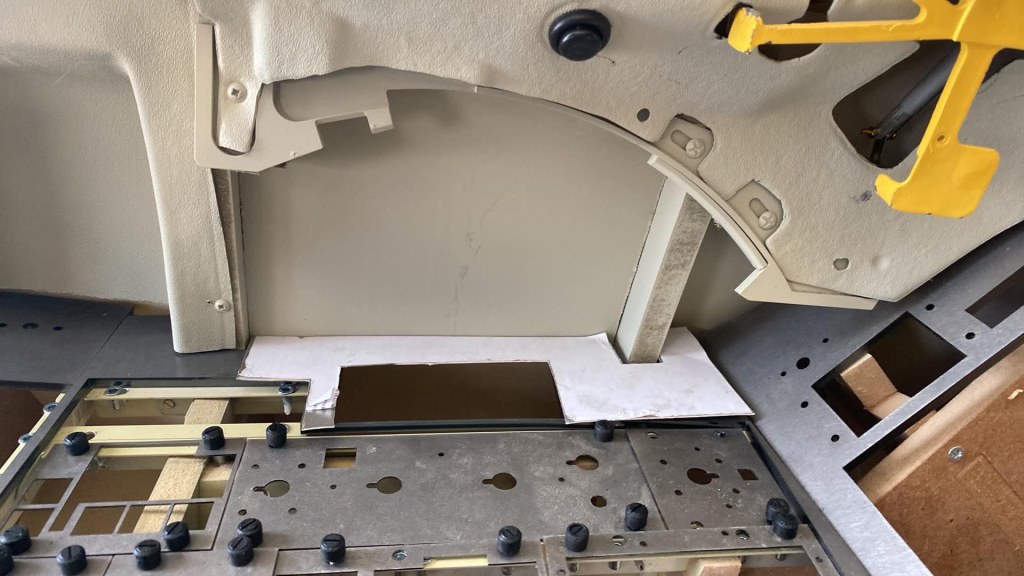
Before going further, I cut the backplates for all panels and tested their fit on the rails of both consoles to make sure everything aligned correctly. This step was long and sometimes frustrating, as the precision of the drilling in the rails was not perfect. In hindsight, I should have machined 1 mm steel plates with the entire DZUS hole pattern pre-drilled, and mounted these under the 6 mm plates. That would have ensured perfect alignment from the start and saved a lot of time.
Specially Machined Parts
Some parts required more advanced machining:
- Throttle grip guide: I fabricated a custom guide with both the afterburner detent and the idle detent, just like in the real jet.
- Throttle lever: The throttle itself was adapted from a Thrustmaster Cougar, mounted on a custom-made replica arm. (This will be covered in more detail in a future article.)
- Auxiliary panels and console contours: These were cut from steel plates. Based on reference photos, I noted that the panel surfaces sit flush with the console surfaces. Since real panels are about 6 mm thick, I chose this same thickness for the steel plates, which also helps reinforce the rigidity of each console module.
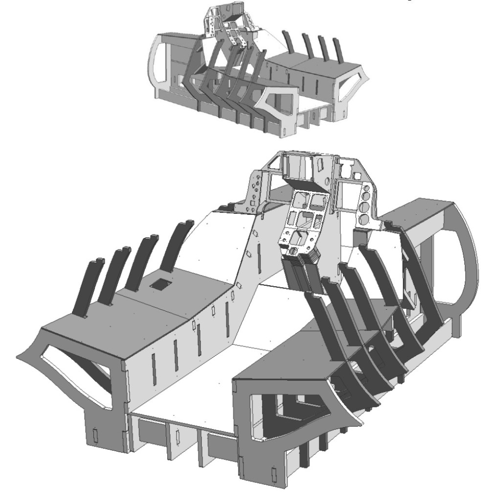
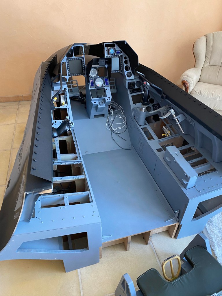
The Structure Components
The cockpit is divided into several main modules:
- Left console
- Right console
- Central floor (supporting the seat)
- Main Instrument Panel (MIP), which in my build was made of steel
- Instrument shroud above the MIP, made of four genuine F-16 parts
- Forward shroud section, completing the front of the structure
Each section is assembled to create a strong but accessible base for mounting electronics, panels, and controls.
Lessons Learned
Planning is everything. Allowing enough clearance, thinking about future maintenance, and simulating real-world mounting systems like DZUS rails will save countless hours down the road. Even with MDF and FOREX, reinforced by steel elements, it’s possible to achieve a realistic, robust cockpit structure—especially once painted and dressed with authentic panels.

Laisser un commentaire